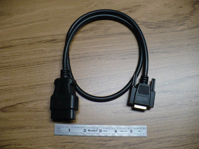
ADVANCED VEHICLE TECHNOLOGIES, Inc.
OBD-II Cable Revision Descriptions
Updated: 9 June, 2002
Note that all OBD-II cable versions prior to the adoption of a molded assembly are not documented. They all preceeded the cables documented here. Those versions included hand made assemblies using a Delphi Packard connector or a Hypertech adapter and a custom cable. If more information is needed about one of those "pre-production" cables, contact the factory. Photos of our current cable assembly, including close-ups of each connector are at the bottom of this page.
Revision A
General release; January, 1998
First production release of fully molded OBD-II cable.
Conductors are 26 AWG.
These cables are easily identified by the fact that the cable is grey and the molded plug is black.
There was only one batch of these cables made.
Only some pins were connected (all pins were populated). Pins not noted in the table were not connected.
DA-15S pin #
J1962 Signal Description
OBD-II pin #
2
J1850 Bus +
2
3
3
4
chassis ground
4
connector shell
shield drain wire
4
5
signal ground
5
6
6
7
K-line of ISO 9141
7
10
J1850 Bus -
10
11
11
13
V-Battery + unswitched
16
15
L-line of ISO 9141
15
Revision B
General release; September, 1998
Fully molded OBD-II cable. Cable is black and molded connectors are black.
Conductors are 22 AWG.
DA-15S pin #
J1962 Signal Description
OBD-II pin #
1
1
2
J1850 Bus +
2
3
3
4
chassis ground
4
connector shell
shield drain wire
4
5
signal ground
5
6
CAN_H of J2284
6
7
K-line
of ISO 9141 and ISO 14230
7
8
8
9
9
10
J1850 Bus -
10
11
11
12
12
13
V-Battery + unswitched
16
14
CAN_L of J2284
14
15
L-line
of ISO 9141 and ISO 14230
15
no connection
13
Revision C
General Release; November, 1999
Changed all conductors from 22 AWG to 24 AWG.
Pin connections same as listed for Revision B.
Revision D
General Release; April, 2001
Removed drain wire (overall foil shield) connection to DA-15S metal shell.
The metal shell of the DA-15S connector is left floating.
This is done to prevent an inadvertent ground connection between the vehicle ground and the host computer ground.
(Models affected: AVT-921, AVT-931, and AVT-512.)
DA-15S pin #
J1962 Signal Description
OBD-II pin #
1
1
2
J1850 Bus +
2
3
3
4
chassis ground
4
no connection
shield drain wire
4
5
signal ground
5
6
CAN_H of J2284
6
7
K-line
of ISO 9141 and ISO 14230
7
8
8
9
9
10
J1850 Bus -
10
11
11
12
12
13
V-Battery + unswitched
16
14
CAN_L of J2284
14
15
L-line
of ISO 9141 and ISO 14230
15
no connection
13
no connection
to connector
metal shell.


OBD-II Cable ~3 meters long.


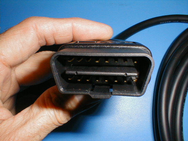
OBD-II cable, J1962 connector end, close-up.


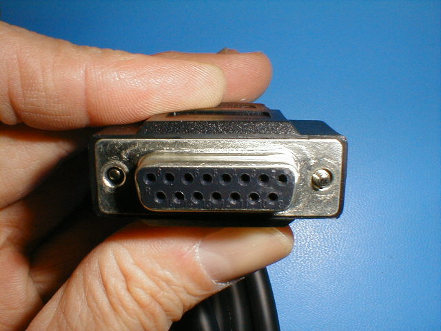
OBD-II cable, DA-15S connector end, close-up.


Site Map