ADVANCED VEHICLE TECHNOLOGIES, Inc.
AVT-423
Hardware Revision Descriptions
Order Number Descriptions
Photos
Updated: 13 May 2024
Notes
General Description
Multiple interface.
Communications to the client computer via Ethernet.
It is equipped with the following:
CAN0: 2-wire, (non-FD).
CAN1: 2-wire or Single Wire (software selected), (non-FD).
CAN2: 2-wire (CAN-FD).
CAN3: 2-wire (CAN-FD).
LIN0: LIN or KWP.
LIN1: LIN or KWP.
The AVT-424 LIN Expansion mezzanine board is now available.
It
adds six channels of LIN communications to the AVT-423.
It can be quickly added to an AVT-423 rev. "F" board.
Flexray (hardware capability exists, but no firmware support).
Flexray will never be developed.
Hardware Configuration
The default hardware configuration of the board is rev. "DA" or
"FA".
The hardware configuration is noted in the white "Rev" block on the top of
the board.
Some hardware configurations are listed below. Other configurations are
available, ask us.
A unique revision level and order number will be assigned for each unique
hardware configuration requested.
PC Board Revision
PC Board Revision
The revision of the PC board is noted in copper on the bottom of the
board.
It only changes when the board is redesigned.
PC Board Revision A0
1 February 2016.
Original board design.
Qty. 2 built.
Never released for production. Prototypes
only.
"A1" - Remove R41. Remove R44.
"A2" - Connect NB-PD2 (NB-P2-32) to NB-UART1_RX (NB-P2-21) to monitor
state of LIN0 bus. Connect NB-PD3 (NB-P2-37) to NB-UART2_RX (NB-P2-31) to
monitor state of LIN1 bus.
PC Board Revision B
18 February 2016.
Changes: Corrected the 3.3 vdc converter (it was upside down); added R53
to Port F0 for ISR timing measurements; Re-sized the board to fit a
Hammond RM2055M enclosure.
Qty. 2 built.
Never released for
production. Pre-production only (early May 2016).
"B1" - Remove R41. Remove R44.
"B2" - Remove R41. Remove R44. Connect
NB-PD2 (NB-P2-32) to NB-UART1_RX (NB-P2-21) to monitor state of LIN0
bus. Connect NB-PD3 (NB-P2-37) to NB-UART2_RX (NB-P2-31) to monitor
state of LIN1 bus.
"B3" - Connect NB-PD2
(NB-P2-32) to NB-UART1_RX (NB-P2-21) to monitor state of LIN0 bus.
Connect NB-PD3 (NB-P2-37) to NB-UART2_RX (NB-P2-31) to monitor state of
LIN1 bus. Replace U23 with a NCP7805TG fixed three-terminal voltage
regulator (very little +5v supply needed, linear regulator is more than
adequate).
PC Board Revision
B2
Date unknown.
Changes:
Corrected the 3.3 vdc converter (again); updated footprints of both
DC/DC converters.
None were built.
Pre-production only (early May 2016).
PC Board Revision C
Late May 2016.
Changes:
Added the solid state relays (switches) to the CAN termination network
for all four CAN channels.
Qty. 100 built.
PC Board Revision D
January 2018.
Changes:
Corrected wiring issues with LIN bus monitor and control signals.
Qty. 300+ built.
PC Board Revision F
December 2020.
Changes:
Added P10 to accommodate the comms signals to the AVT-424 LIN
Expansion mezzanine board.
Added JP1 and JP2 to allow an alternate source for the VBATT
supply for LIN0 and LIN1.
Qty. 100 built (so far).
Circuit Configuration - for board rev. "F" only
The "PC board revision" is noted in copper on the bottom
of the board.
The "Circuit Configuration Revision" is noted in the white block on the
top of the board.
Revision
|
Notes
|
CAN0 (non-FD)
|
CAN1 (non-FD)
|
CAN2 (FD) |
CAN3 (FD) |
LIN0 or KWP0
(Channel 7 or 8) |
LIN1 or KWP
(Channel 5 or 6) |
AVT-424 |
Flexray |
FA
|
. |
2-wire
(ISO11898)
|
2-wire (ISO11898)
or SWC
[software selected]
|
2-wire
(ISO11898) |
2-wire
(ISO11898) |
Installed
|
Installed. |
Not installed. |
Not installed.
|
| FB |
Will never be
available.
|
|
|
|
|
|
|
|
(note 1)
|
| FC |
(note 2) |
2-wire
(ISO11898) |
2-wire (ISO11898)
or SWC
[software selected] |
2-wire
(ISO11898) |
2-wire
(ISO11898) |
Installed
|
Installed. |
Installed.
|
Not installed. |
| FD |
(note 3) |
2-wire
(ISO11898) |
2-wire (ISO11898)
or SWC
[software selected] |
2-wire
(ISO11898) |
2-wire
(ISO11898) |
Installed.
|
Installed.
|
Installed.
|
Not installed. |
| FF |
(note 4) |
2-wire
(ISO11898) |
2-wire (ISO11898)
or SWC
[software selected] |
2-wire
(ISO11898) |
2-wire
(ISO11898) |
Installed. |
Installed. |
Installed. |
Not installed. |
| FG |
(note 5) |
2-wire
(ISO11898) |
2-wire (ISO11898)
or SWC
[software selected] |
2-wire
(ISO11898) |
2-wire
(ISO11898) |
Installed. |
Installed. |
Installed. |
Not installed. |
NOTES
1 - Flexray will never be available.
2 - Add LIN expansion board.
Refer to rev. "FC" modification instructions.
3 - Separate LIN0 and LIN1
supply/reference voltage sources.
Refer to rev. "FD" modification instructions.
After modification:
LIN0 supply is on
P3 pin 8.
LIN1 supply is on P3 pin 9.
4 - Add a solid
state relay controlled by software command.
The solid state relay is connected to P3 pins 6 and 19.
Used to control or signal off-board hardware.
Refer to rev. "FF" modification instructions.
5 - Over-voltage protection zener diode D18 has been
changed to a +18 volt device.
As of 14 March 2023, this will be the standard ship configuration.
6 - xxx.
7 - xxx.
Circuit Configuration - for board rev. "D" only
The "PC board revision" is noted in copper on the bottom
of the board.
The "Circuit Configuration Revision" is noted in the white block on the
top of the board.
Revision
|
Notes
|
CAN0 (non-FD)
|
CAN1 (non-FD)
|
CAN2 (FD) |
CAN3 (FD) |
LIN0 or KWP0
(Channel 7 or 8) |
LIN1 or KWP
(Channel 5 or 6) |
Flexray |
DA
|
. |
2-wire
(ISO11898)
|
2-wire (ISO11898)
or SWC
[software selected]
|
2-wire
(ISO11898) |
2-wire
(ISO11898) |
Installed.
|
Installed. |
Not installed.
|
| DB |
Will never be
available.
|
2-wire
(ISO11898) |
2-wire (ISO11898)
or SWC
[software selected] |
2-wire
(ISO11898) |
2-wire
(ISO11898) |
Installed. |
Installed. |
(note 1)
|
| DC |
Only one ever built.
(note 2) |
2-wire
(ISO11898) |
2-wire (ISO11898)
or SWC
[software selected] |
2-wire
(ISO11898) |
2-wire
(ISO11898) |
Installed.
|
Installed. |
Not installed.
|
| DD |
Only one ever built.
(note 3) |
2-wire
(ISO11898) |
2-wire (ISO11898)
or SWC
[software selected] |
2-wire
(ISO11898) |
2-wire
(ISO11898) |
Installed.
|
Installed. |
Not installed.
|
| DF |
Only one modified.
(note 4)
|
2-wire
(ISO11898) |
2-wire (ISO11898)
or SWC
[software selected] |
2-wire
(ISO11898) |
2-wire
(ISO11898) |
Installed. |
Installed. |
Not installed. |
NOTES
1 - Flexray will never be available.
2 - Added mating sockets (P4, P5, P6, P7, P8, P9) for
AVT-424 LIN expansion board. Added the following wires from the
AVT-423 board to AVT-424 P3.
U18-93 --- (red) --- P3-1
U18-92 --- (blu) --- P3-2
U18-91 --- (wht) --- P3-3
U18-94 --- (yel) --- P3-4
R45-1 (opposite J4-4) --- (yel)
--- P3-5
U18-6 --- (wht) --- P3-6
3 - Added modifications of
note 2 (above).
Performed the
following modifications to break out the LIN bus supply.
Top of board.
Cut the following tracks between:
D17 cathode
& D6 anode.
D6 anode
& D5 anode.
D5 anode
& D4 anode.
Top of board.
Add the following wires, between:
D5 anode to P3-8.
(LIN0 transceiver)
D6 anode to
P3-9. (LIN1 transceiver)
D4 anode to D17
cathode. (SWC transceiver)
4
- Over-voltage protection zener diode D18
changed to a +18 volt device.
5 - xxx.
6 - xxx.
Circuit
Configuration
- for board rev. "C" only
The "PC board revision" is noted in copper on the bottom
of the board.
The "Circuit Configuration Revision" is noted in the white block on the
top of the board.
Revision
|
Notes
|
CAN0 (non-FD)
|
CAN1 (non-FD)
|
CAN2 (FD) |
CAN3 (FD) |
LIN0 or KWP
(Channel 5 or 6) |
LIN1
(Channel 7) |
Flexray |
CA
|
Mod note 3. |
2-wire
(ISO11898)
|
2-wire (ISO11898)
or SWC
[software selected]
|
2-wire
(ISO11898) |
2-wire
(ISO11898) |
Installed
|
Installed |
Not installed.
|
| CB |
Mod note 3. |
2-wire
(ISO11898) |
2-wire (ISO11898)
or SWC
[software selected] |
2-wire
(ISO11898) |
2-wire
(ISO11898) |
Installed |
Installed |
Installed
(note 2)
|
NOTES
1 - Can be added at a later date. Additional
hardware costs will apply.
2 - Hardware and software
not available at this time.
3 - Remove R41. Remove R44. Install wire P2-32 to
P2-21. Install wire P2-37 to P2-31. Replace U23 with NCP7805TG4.
4 - xxx.
Order
Number Descriptions
AVT-423-006 : AVT-423 interface board, installed in enclosure.
Status: Normally a stock item.
AVT-423-007 : AVT-423 interface board only, no enclosure.
Status: Normally a stock item.
AVT-423-047 : AVT-423
interface board rev. 'FD', no enclosure..
Status: Call the factory for status and lead time.
Photos


AVT-423 rev. "DA" board only.
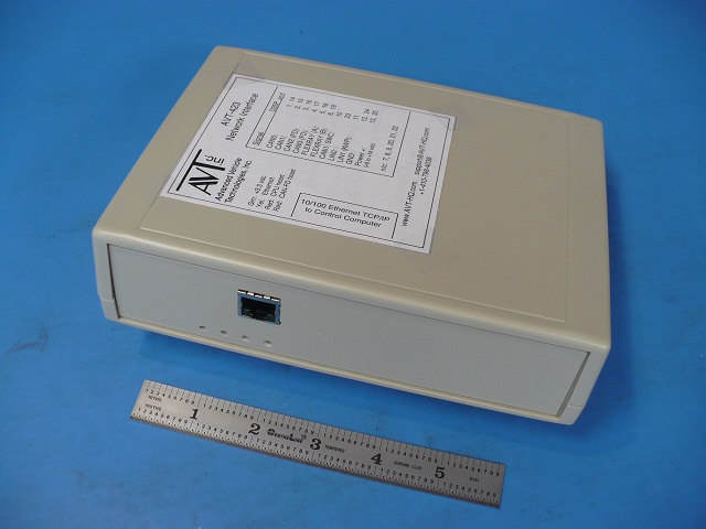
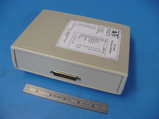
AVT-423 board in enclosure.


AVT-423 rev. "FB" board only.


AVT-423 rev. "FB" board with AVT-424
installed.
Site
Map